
Space tile / module
Galaxia® Tile
Tile built around the same FPGA as the Galaxia development board so it can be designed into missions or advanced prototyping/test solutions.
Technical specifications available
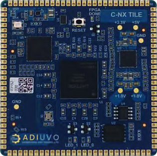
Specifications describe the product architecture. Availability, radiation configuration, performance and qualification evidence are confirmed during mission review. DANU product flight heritage is not claimed.
Tile specifications
| Supply voltage | 4.5 to 18 V |
|---|---|
| Debug interface | Onboard UART debug interface |
| FPGA | Lattice Certus™-NX LFD2NX-40 |
| Configuration Memory | 256 Mbit QSPI |
| Indicators | Done LED and two user LEDs |
| Debug | USB JTAG |
| Carrier requirement | USB connector needed on carrier board |
| Oscillator | 100 MHz |
| Clocking | Other global clock pins broken out via I/O |
| Control | Reset button |
| PSRAM | 32 Mbit |
| I/O | 82 I/O including power and ground, JTAG, 32 I/O at 3v3, 41 I/O configurable voltage (3v3-1.2V and LVDS) |
Further capability
| Capability | Clock generation up to 65 MHz reference clock using the PIO |
|---|---|
| Capability | Communications emulation of a differential backplane bus |
| Capability | Communications monitoring and logging |
| Capability | Sensor emulation across the system and implementation of failure modes |
| Capability | Complex communications creation: implementation of a SpaceWire communication protocol between the FPGA and the Pico |
| Capability | Power management and monitoring of the power network and dissipated power under load or beam-line testing |
Tile capability
- Clock Generation — Generation of up to 65 MHz reference clock using the PIO.
- Communications emulation — Emulation of a differential backplane bus.
- Communications Monitoring — Monitoring and logging communications.
- Sensor emulation — Emulation of sensors across the system and implementation of failure modes.
- Complex communications creation — Implementation of a SpaceWire communication protocol between the FPGA and the Pico, providing a simple interface controlled over USB communication.
- Power management and monitoring — Monitoring the power network, to control, monitor and observe dissipated power as the FPGA design is used under load or test conditions.
NEXT MISSION. NEW POSSIBILITIES.
What are you
building for orbit?
Bring us your mission constraints.
Let’s engineer the compute around them.